Manufacturing
Home / Manufacturing
Shop-floor documentation — the standardized cell concept, equipment, materials, fixturing, quality, and safety. Our current proving ground is the Alpha Facility, described below; as we add facilities they follow the same standardized cell model.
Pages
| Page | Description |
|---|---|
| Facility Layout & Equipment | Floor plan, machines, and support equipment |
| Stock & Fixturing | Billet stock, vises, and SLS soft jaws |
| Tooling Strategy | The standardized 120-tool library |
| Materials | Material strategy and stock specifications |
| Quality Control | Inspection, metrology, and QC process |
| Safety | Shop-floor safety — required reading for everyone |
| Targets & Scaling | Throughput targets and scaling plan |
Standardized Cell Concept
Anvil deploys identical, standardized manufacturing cells designed for predictable, scalable throughput. Each cell is a self-contained production unit with identical machine configuration, tooling, fixturing, and control systems. This standardization is the foundation that enables end-to-end automation: from AI-CAM generation through machining to automated inspection, every step operates against known, fixed parameters. Adding capacity means deploying additional machines into the cell or replicating the cell at a new facility.
Cell Configuration
| Parameter | Specification |
|---|---|
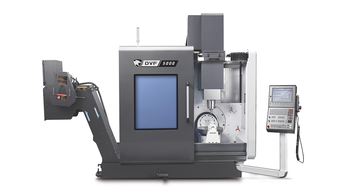
| Machine Platform | DN Solutions DVF 5000 (5-axis vertical) |
| Spindle Interface | HSK-A63, 18,000 RPM |
| ATC Capacity | 120 tools per machine (identical loadout) |
| Controller | Siemens Sinumerik One |
| Work Envelope | 500 x 400 x 459 mm (19.7 x 15.7 x 18.1 in) |
| Table | 540 mm diameter rotary |
| Material | 6061-T651 aluminum (single-material strategy) |
The single-material strategy (6061-T651) eliminates material mix-up risk, simplifies AI-CAM automation with one set of feeds, speeds, and tool life parameters, and reduces stock management complexity. 6061-T651 covers the vast majority of prototype and low-volume production needs for robotics, aerospace, and industrial hardware customers.
Alpha Facility Overview
The Alpha Facility is the initial proving ground for Anvil operations. It is an 8,000 square foot space designed for phased machine deployment, beginning with a single DVF 5000 in July 2026 and scaling to 3 machines by May 2027. The Alpha Facility operates at startup-appropriate parameters: 5 days/week, 8 hours/day, with availability and efficiency ramping as the team learns.
| Parameter | Specification |
|---|---|
| Facility Size | 8,000 sq ft |
| Max Machines | 5 (3 deployed in first year) |
| Operating Schedule | 5 days/week, 8 hours/day |
Phased Machine Deployment
Machines are deployed incrementally as the operations team proves readiness, the AI-CAM automation rate improves, and customer demand materializes.
| Milestone | Target Date | Machines |
|---|---|---|
| Machine 1 deployed | Jul 2026 | 1 |
| Machine 2 deployed | Dec 2026 | 2 |
| Machine 3 deployed | May 2027 | 3 |
| Transition to Facility 1 (MA) | Sep 2027 | 3 + Facility 1 machines |
Utilization Ramp
The plan assumes conservative ramp-up of machine availability and spindle efficiency as the team gains experience and the AI-CAM system matures:
| Month | Machine Availability | Spindle Efficiency | Effective Utilization |
|---|---|---|---|
| Nov 2026 (Month 5) | 45% | 45% | 20% |
| Jan 2027 (Month 7) | 55% | 50% | 28% |
| Mar 2027 (Month 9) | 55% | 55% | 30% |
| Jun 2027 (Month 12) | 60% | 65% | 39% |
| At-Scale Target | 80% | 90% | 72% |
Production Workflow
sequenceDiagram
    participant Customer
    participant Portal as Order Intake
    participant CAM as AI-CAM
    participant SLS as SLS Printers
    participant Stock as Stock Area
    participant Machine as DVF 5000
    participant Deburr as Deburr / Finish
    participant Metro as Metrology Lab
    participant Ship as Shipping

    Customer->>Portal: Upload STEP/IGES
    Portal->>CAM: Geometry + order
    CAM->>Stock: Billet selection
    CAM->>SLS: Soft jaw geometry (if Op 2 needed)
    Stock->>Machine: Billet cut & staged
    SLS->>Machine: Printed soft jaws
    Machine->>Machine: Op 1 — roughing & features (Makro-Grip vise)
    Machine->>Machine: Op 2 — back-side features (soft jaws)
    Machine->>Deburr: Edge break, tumble finish
    Deburr->>Metro: Final QC
    Metro->>Ship: Inspected part + report
Ship->>Customer: Part delivered| Step | Activity | Automation Level |
|---|---|---|
| 1. Order Intake | Customer uploads STEP/IGES via portal. Geometry validation and instant quoting. | Fully automated |
| 2. DFM Review | Manufacturability check against DVF 5000 envelope, tool access, tolerances. | Automated + human override |
| 3. AI-CAM Generation | Toolpaths generated against fixed 120-tool library. Stock selection, fixturing plan. | Automated (target 80%+) |
| 4. Soft Jaw Queue | If second op required, jaw geometry auto-designed and queued to Fuse SLS. | Automated |
| 5. Job Scheduling | ERP/MES orchestrates machine queue with load balancing. | Automated |
| 6. Billet Prep | Billet pulled from stock, cut if needed, stamped, staged at machine. | Manual |
| 7. Op 1 Machining | Billet loaded, touch probing for datum. Thriller thread mills, full cycle. | Auto machining, manual load |
| 8. Op 2 Machining | SLS soft jaws installed, part loaded, probing, back-side features. | Auto machining, manual load |
| 9. Deburr/Inspect | Edge break, tumble finish. Route to metrology lab for final QC. | Manual |
| 10. Ship | Digital inspection report attached. Customer portal updated. | Auto reporting, manual pack |