Soft Jaw Generation¶
Home / Engineering / System Design / Soft Jaw Generation
Status
Working prototype — accurate to the code as of 2026-06-11.
This is the single reference for the soft-jaw generation feature. It covers what it produces and why (§1), the code map (§2), the geometric model (§3), the pipeline end to end (§4–6), the design decisions and their rationale (§7), the tunables (§8), known limitations (§9), and how it's verified (§10). §1, §3, and §7 are the high-level read; §4–6 are the details.
1. What this is and why it exists¶
A machined part is typically made in two setups:
- Op1: a raw billet is clamped in a vise and everything reachable from above is machined. The result is the part plus leftover material ("stock") wherever op1's tool couldn't reach — typically lower side walls, regions shadowed by the op1 grip, and webs between features.
- Op2: the workpiece is flipped/re-gripped and the remaining stock is machined.
Op2's problem is workholding: the op1 output is no longer a rectangular billet, so plain vise jaws can't grip it well, and gripping an unfinished (still-proud) surface positions the part wrong. Soft jaws are custom vise jaws with a pocket that conforms to the part, gripping it on finished faces while leaving all remaining stock exposed above the jaw for the op2 spindle.
This pipeline generates a left/right soft-jaw pair automatically from two inputs and exports them as STLs. The jaws are 3D printed, not milled — this decision shapes several design choices (§7.5, §7.6).
inputs:   <part>.step          final part        (design intent, loaded via Parasolid)
          <part>_op1.stl       post-op1 workpiece (CAM stock simulation)
outputs:  out/<part>_right.stl  +X jaw
          out/<part>_left.stl   -X jaw
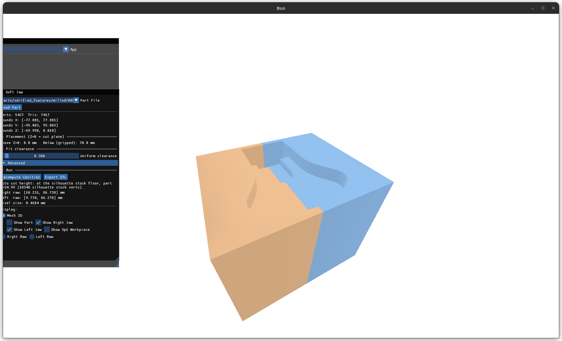
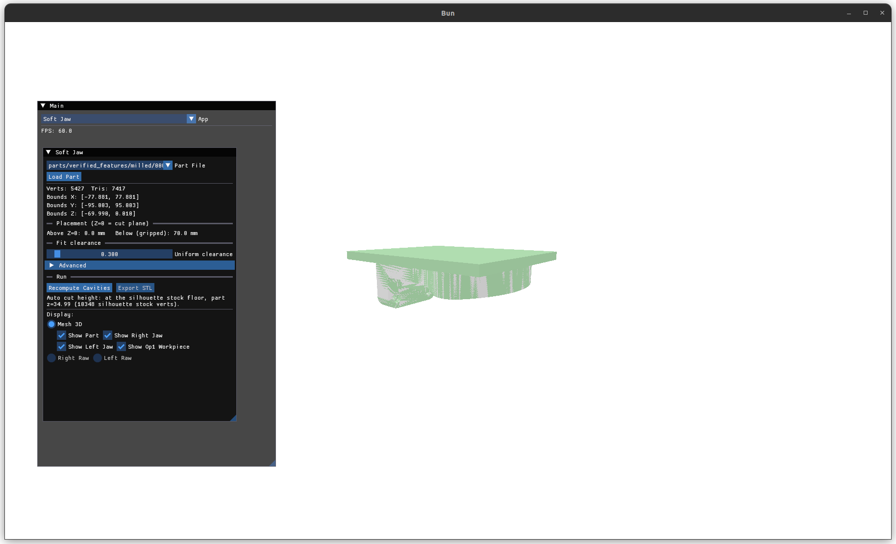 The "Show Op1 Workpiece" overlay (green) on the loaded part (gray): the final part
(design intent) and the post-op1 workpiece superimposed. The op2 problem is
everything the workpiece still has that the part doesn't — the stock to be removed,
green where it stands proud — plus how to grip what's already finished. The panel
reads back the bounds, the placement (0 mm above Z=0, 70 mm gripped below), and the
derived cut height.
The "Show Op1 Workpiece" overlay (green) on the loaded part (gray): the final part
(design intent) and the post-op1 workpiece superimposed. The op2 problem is
everything the workpiece still has that the part doesn't — the stock to be removed,
green where it stands proud — plus how to grip what's already finished. The panel
reads back the bounds, the placement (0 mm above Z=0, 70 mm gripped below), and the
derived cut height.
The hard problem is not the pocket — it's deciding the cut height: the horizontal plane that splits "gripped below" from "exposed above". Everything op2 still has to machine must end up above it; everything the jaw touches below it must be finished surface. The pipeline derives this plane purely geometrically by comparing the workpiece mesh against the final part mesh ("label-free" — §7.1).
2. Code map¶
| Layer | Files | Contents |
|---|---|---|
| App (GPU/UI/orchestration) | source/app_soft_jaw.cpp |
Background load worker, registration driver, placement, rasterization, UI, export, headless harness. Unity-built via mach_apps.h (app index 0, "Soft Jaw"). |
| Pure decision math | source/machen/mach_softjaw.{h,cpp} |
RegisterWorkpieceOffsetSeed, RefineRegistrationOffset, ValidateRegistration, SilhouetteStockZs, RobustStockFloorZ, ApplyFitClearance, FillToPartingPlane, WorkpieceStlPathForPart. No GPU/Parasolid — unit-tested in machen_tests. |
| Mesh utilities | source/machen/mach_mesh.{h,cpp} |
ReadStl/WriteBinaryStl, ClosestDistanceToMesh/IsWithinDistanceOfMesh (+ trimesh_dist_grid accelerated overloads), SubdivideLongEdges, WeldVertices, BuildHeightfieldPrism. Unit-tested. |
| GPU rasterizer | source/machen/mach_depth_map.{h,cpp} + assets/shaders/depth_capture.slang |
Orthographic depth maps (shared with other apps). |
Tests: source/tests/test_mach_softjaw.cpp, source/tests/test_mach_mesh.cpp.
3. The geometric model¶
All units are millimeters (matching mach_cad's STEP output). All frames are
right-handed. The part's CAD frame is the jaw frame — we never rotate, only
translate:
- +Z is the op2 spindle axis. Stock must be reachable from +Z.
- ±X is the clamp axis. The right jaw approaches from +X, the left from −X. The vise closes along X.
- World Z = 0 is the cut plane. The jaws exist entirely below it; nothing of the jaw ever rises above Z = 0.
- The parting plane is the vertical X plane where the two closed jaws meet — the X-center of the placed part bounds (not the workpiece bounds, which sit asymmetrically when stock margins differ), which lands at X ≈ 0 because placement centers the part.
The only transform applied to the part is a translation PartTranslation
(SoftJawComposePartXf): X/Y center the part AABB on the origin; Z places the
derived cut height at world Z = 0. One source of truth feeds the 3D preview, the
cavity computation, and the export, so they cannot drift apart.
Each jaw is a heightfield prism: a solid block whose inner face is a depth map of the workpiece viewed along the clamp axis, opened by a fit clearance, with all non-part area filled solid to the parting plane. By construction a heightfield has no undercuts along X, which is exactly the printable/insertable geometry class we want (§7.6).
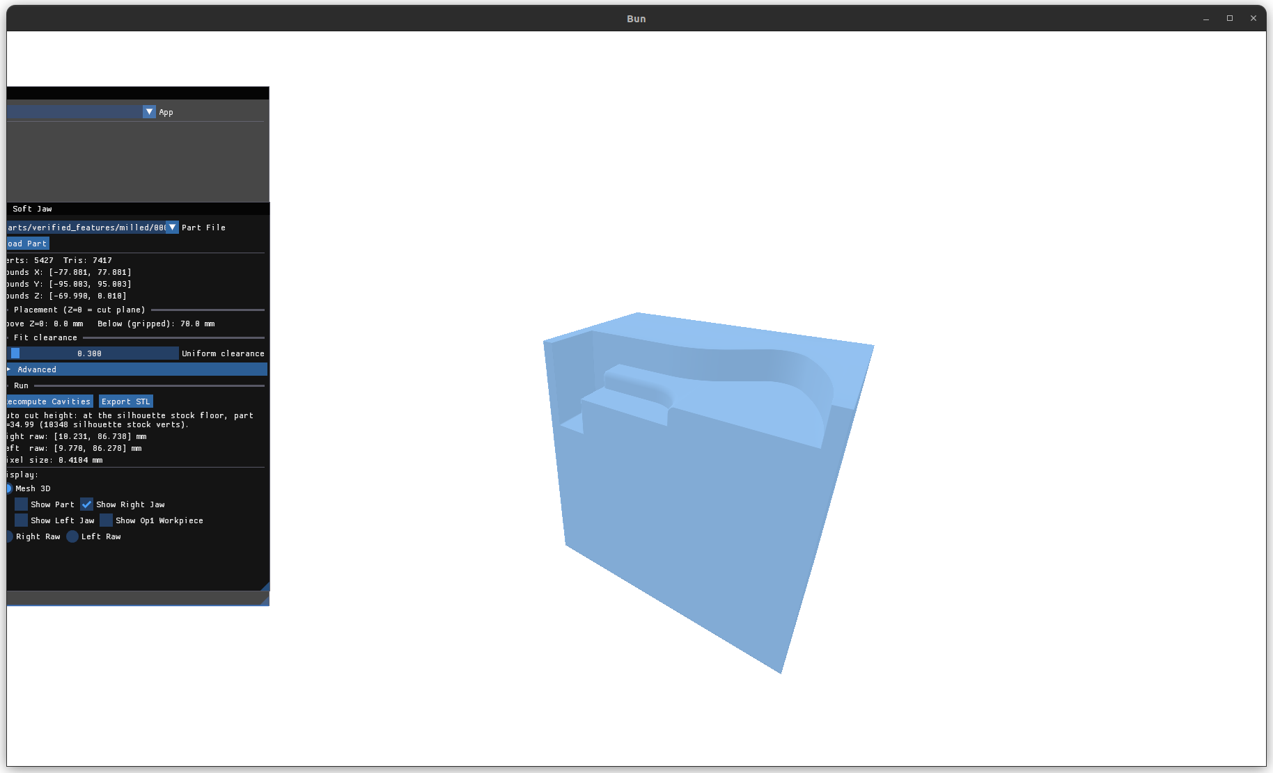
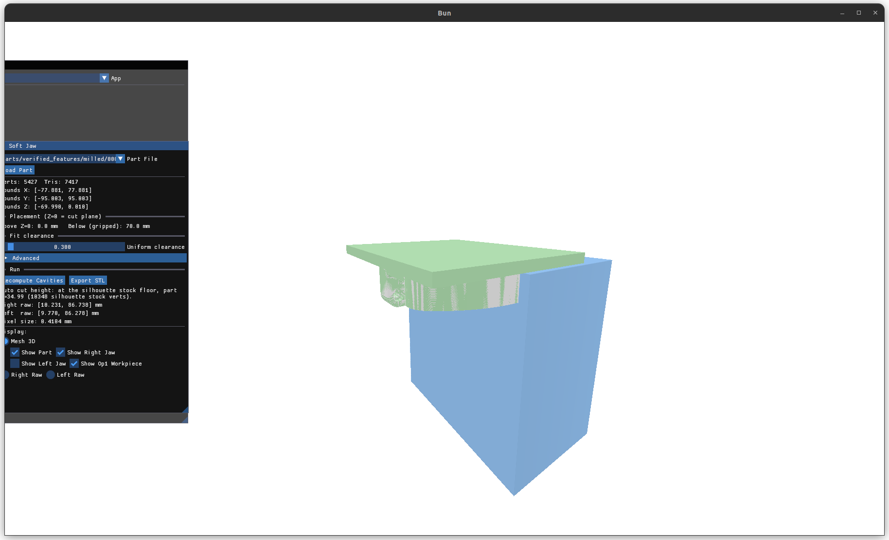 The right jaw (blue) closed onto the part with its op1 workpiece overlaid (green).
Everything below the Z = 0 cut plane is held by the conforming pocket; everything
above stays exposed for the op2 spindle.
The right jaw (blue) closed onto the part with its op1 workpiece overlaid (green).
Everything below the Z = 0 cut plane is held by the conforming pocket; everything
above stays exposed for the op2 spindle.
4. Pipeline overview¶
                      ┌─ background load worker (per part) ──────────────────┐
 STEP ──Parasolid──►  │ part mesh (BodyMesh)                                 │
 _op1.stl ──ReadStl─► │ workpiece mesh                                       │
                      │   1. registration: workpiece → part frame  (§5.1)    │
                      │   2. stock flags: bounded-pitch sampling    (§5.2)   │
                      │   3. silhouette filter: jaw-relevant stock  (§5.3)   │
                      └──────────────────────────────────────────────────────┘
                      ┌─ main thread, on adopt (copy cost only) ─────────────┐
                      │   4. cut height: robust stock floor         (§5.4)   │
                      │   5. placement: PartTranslation             (§5.5)   │
                      └──────────────────────────────────────────────────────┘
                      ┌─ "Recompute Cavities" (or auto) ─────────────────────┐
                      │   6. depth-map rasterization per side       (§6.1)   │
                      │   7. fit clearance + fill to parting plane  (§6.2)   │
                      │   8. heightfield prism mesh                 (§6.3)   │
                      │   9. export binary STLs                              │
                      └──────────────────────────────────────────────────────┘
Steps 1–3 are expensive, so they all run once per load in a worker thread — the only thing that crosses to the main thread is the silhouette Z list (plus the meshes for display). Steps 4–5 are trivial and run on adopt; 6–9 run on demand and use the GPU. The dense sampling copy from step 2 never leaves the worker: display, rasterization, and export all keep the original CAM mesh.
5. Cut-height derivation (the decision pipeline)¶
5.1 Registration: workpiece → part frame¶
The op1 STL comes from our own pipeline in the part's frame, but CAM exports generally sit in a translated machine frame. We register by translation only (§7.2):
- Seed (
RegisterWorkpieceOffsetSeed): op2 only removes material, so the part AABB must fit inside the workpiece AABB (withinContainTol= 2 mm). If containment already holds, the seed is zero — a co-registered workpiece must not be moved (center-aligning would shift it when stock margins are asymmetric). Otherwise try aligning AABB centers. If containment still fails, the workpiece is dropped entirely and no jaws are generated (§5.5). - Refinement (
RefineRegistrationOffset): coordinate descent minimizes the median distance of ~128 strided workpiece-vertex samples to the part mesh: three rounds of per-axis greedy walks (±direction, keep stepping while improving, up toSpan= 20 mm travel), with step shrinking 1 → 0.2 → 0.04 mm and span 20 → 8 → 3.2 mm. Final resolution 0.04 mm vs the 0.05 mm finish tolerance. The median objective is robust as long as ≥ 50 % of sampled workpiece vertices lie on finished surfaces; the residual gate below catches the rest (§9.2). - Validation (
ValidateRegistration): a locked-on registration has its finished faces ON the part, so the final median residual must be ≤ResidualTol(0.2 mm) and the part AABB must still sit inside the moved workpiece's AABB (the walk can travel ±20 mm). Either failure rejects the workpiece with the reason logged; the residual is always logged (real parts lock on at ~0.007–0.017 mm).
5.2 Stock detection: bounded-pitch surface sampling¶
Op2 only removes material, so the workpiece surface is on-or-outside the part surface everywhere. The unsigned distance from a workpiece point to the part surface is the local stock allowance:
- First, the workpiece mesh is midpoint-subdivided (
mesh::SubdivideLongEdges, 4-way, until no edge exceedsSampleEdge= 5 mm). A per-vertex test sees nothing between the vertices of huge CAM triangles — a proud slab whose corners all touch finished surfaces flags zero vertices — so subdivision turns the per-vertex loop into a ≤ 5 mm-pitch sample of the whole surface. It's then welded (mesh::WeldVertices, exact-bits merge — STL corners and subdivision midpoints are bit-deterministic copies): unwelded duplicates would multiply distance queries and make every sorted silhouette Z a "dense pair", silently disabling the stray trim (§5.4). The subdivided copy is worker-local; only the silhouette Zs leave the worker, so display/rasterization/export keep the ~30× lighter original CAM mesh. - For every workpiece vertex, "is it within
FinishTolof the part surface?" viamesh::IsWithinDistanceOfMeshon amesh::trimesh_dist_gridbuilt once over the part mesh (§7.8): only the 1–8 grid cells withinFinishTolof the point are inspected, then exact point-to-triangle distance (Ericson Voronoi-region test) with an early return at the first triangle within tolerance — O(1) per query. d > FinishTol(0.05 mm) ⇒ the vertex is stock; else finished.FinishTolmust exceed the STL chord error plus the part-meshing deflection (0.01), hence 0.05.
This produces a per-vertex stock flag array parallel to the subdivided workpiece
vertices. The sampling pitch bounds what can hide: a proud feature must span less
than SampleEdge in every surface direction to escape sampling entirely. (The
green in the §1 overlay is exactly these proud regions; the cut height must land
below the lowest green a jaw could trap — §5.3–5.4.)
5.3 Silhouette filter: which stock can a jaw wall in?¶
The jaws wrap the workpiece from ±X below the cut plane, so only stock on the ±X silhouette can be trapped by a jaw. Stock inside pockets or on top faces is reached by the +Z spindle from above at any cut height and must not drag the grip line down.
SilhouetteStockZs approximates occlusion on a (y, z) grid (cell 0.5 mm, capped at
2048² — the cap coarsens cells on parts larger than ~1 m):
- Every triangle splats its x-extent into every cell its (y, z) bounding box touches (so large flat walls with vertices only at corners still occlude the cells behind them).
- A stock vertex counts as silhouette when its x is within
SkinTol(1 mm) of its cell's extreme on either side — or when its cell is empty (conservative: lone geometry counts).
Output: the Z values of silhouette stock vertices. The cell size is the smallest stock step height the test can resolve: a proud step shorter than one cell sitting just below taller outboard geometry (e.g. a billet wall above the cut) shares its cell, the wall's splat owns the cell extreme, and the step is shadowed — so the cell must stay below any stock feature that must end up above the cut.
5.4 Cut height: robust stock floor¶
Every silhouette stock vertex must end up above the cut, so the cut goes at the
lowest silhouette stock Z (RobustStockFloorZ), with a density-aware bottom trim
so rim-misclassified strays can't drag the cut to the part bottom. Real stock is a
surface patch, so its Zs cluster tightly; strays are lone points. Walking up from the
sorted bottom, a value is trimmed only while (a) the trim budget allows —
max(3, OutlierFrac·N), floored because strays don't scale with sample count and a
pure 1 % fraction silently disables the trim below 100 samples — and (b) the next
value above is more than StrayGap (7.5 mm) away (isolated). The walk stops at the
first dense pair, so a real low stock patch survives even when the count budget would
have allowed deleting it. Wrongly keeping a stray only moves the cut down (safe). The
app then subtracts CutMargin (0.01 mm) so remaining stock stands slightly proud of
the jaw's top face rather than flush. (Residual limitation: a real stock patch
represented by a single isolated vertex is indistinguishable from a stray and gets
trimmed.)
This replaced an earlier "top stock band" descent that stopped at the first Z gap > 12 mm; that buried a dense second stock band below the top one on a real part. Robust-min's failure direction is the safe one — a dense cluster of misclassified low verts cuts too low (weaker grip, stock still accessible) instead of burying real stock (scrap part).
5.5 Placement — no fallback jaws¶
SoftJawRecenterPart: T.x/y = −part-AABB-center, T.z = −CutZ, and PlacementOk
becomes true. Jaws exist if and only if the auto cut height was derived — when
any of the following hold, PlacementOk stays false, "Cannot generate jaws: PlacementStatus) and on stdout, the Recompute button is
disabled, SOFTJAW_AUTO prints failed, and nothing is exported:
- no paired workpiece STL / STL-only load / registration rejected (§5.1),
- no proud vertices (workpiece == part: nothing left to machine),
- no silhouette stock (all remaining stock is interior/top-facing),
- the stock floor reaches the part bottom (no finished band to grip).
The part itself stays loaded and viewable (placed top-at-Z=0, display only).
Rationale: a cavity molded on anything but a registered op1 workpiece at a derived
cut height either misfits the real clamped lump or buries stock — both worse than
refusing (§7.9). The placed part's own AABB is kept separately (PartBoundsMin/Max)
for the panel readout and the parting plane; BoundsMin/Max tracks the (larger)
cavity source for the raster window.
6. Jaw geometry generation¶
6.1 Depth-map rasterization¶
For each side, SoftJawPlaneForSide builds an orthographic raster plane:
- Right jaw: origin at (+X bound + 5 mm margin), U sweeps −Y, V sweeps +Z, normal −X. Left jaw is the mirror (normal +X). Both keep V along +Z so image-vertical = Z; Y appears mirrored between sides, which is physically correct (you're looking from opposite sides).
- MaxZ is pinned at 0: nothing above the cut plane is ever rasterized, so no jaw geometry can rise above it. Workpiece geometry above Z = 0 clips out at the image edge.
- The rasterizer requires a square image (|U| = |V|), so the shorter axis is padded — Y symmetrically, Z downward only (never raising MaxZ); the padding region is filled solid later anyway. Consequence: jaw block dimensions are an artifact of this squaring, not real jaw blank stock (§9.6).
geom::ComputeDepthMap renders the original workpiece mesh on the GPU:
orthographic projection, near plane at the raster plane, fragment shader writes the
analytic forward distance, depth test less_or_equal keeps the nearest surface, cull
off. Because placement is a pure translation, the raster plane is shifted by −T into
the workpiece's frame and the depth map re-framed onto the world plane afterwards — a
translation changes neither the plane axes nor the depths. Pixels with no geometry
hold the sentinel 1e30 (anything ≥ 1e29 is treated as "no part here"). Default
resolution 512×512; pixel size = plane extent / 512 (≈ 0.28 mm on a 145 mm plane).
Power-of-two sizes only (asserted). If every pixel is the sentinel (no part below
Z = 0 at all), the jaw build is skipped and flagged rather than exporting a
degenerate flat slab.
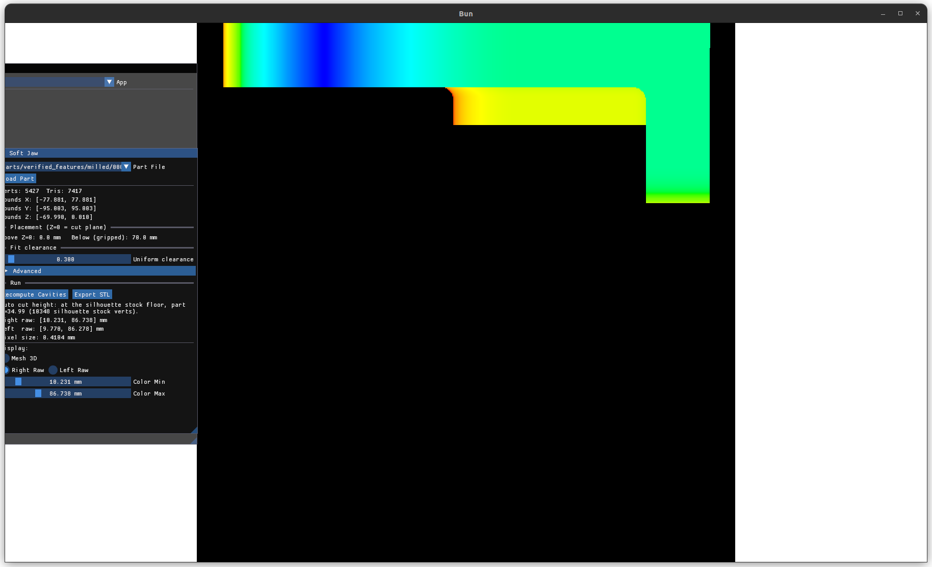
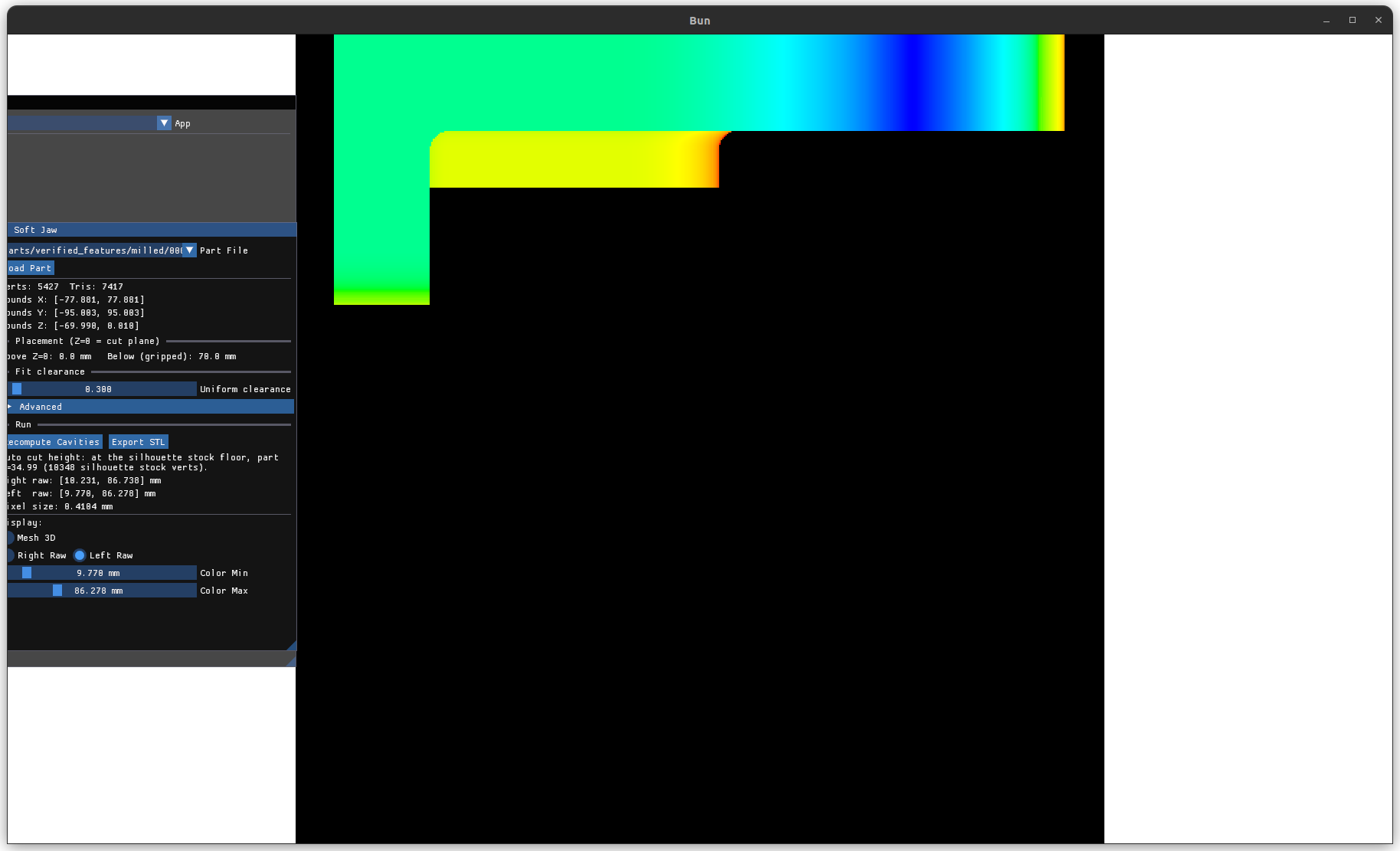 The right (top) and left (bottom) raw depth captures — each a heightfield of the
workpiece viewed along its clamp axis, color-mapped by forward distance to the
raster plane (warm = nearer, cool = farther; black = the no-part sentinel). Y is
mirrored between the two sides because you're looking from opposite directions.
These become the conforming inner faces of the two jaws.
The right (top) and left (bottom) raw depth captures — each a heightfield of the
workpiece viewed along its clamp axis, color-mapped by forward distance to the
raster plane (warm = nearer, cool = farther; black = the no-part sentinel). Y is
mirrored between the two sides because you're looking from opposite directions.
These become the conforming inner faces of the two jaws.
6.2 Heightfield post-ops (pure, unit-tested)¶
Order matters; both operate on a CPU copy of the raw map:
ApplyFitClearance: every finite pixel recedes toward the raster plane byFitClearance(default 0.3 mm), clamped at 0. This opens a uniform gap along the clamp axis only (§7.5). Sentinels stay untouched.FillToPartingPlane: every sentinel pixel becomes solid out to the parting plane — fill depth is the travel from the raster plane to x = PartingX along the view normal. Result: the jaw is a solid block whose only recess is the conforming pocket; the two jaws' filled regions meet exactly at the parting plane when closed.
6.3 Heightfield prism (mesh::BuildHeightfieldPrism)¶
Builds a closed, oriented-manifold triangle mesh from the N×N heightfield:
- N² inner vertices at pixel centers — pixel (i,j) →
(i+0.5)/Nof the plane, matching where the GPU rasterizer actually sampled each depth (a corner-conventioni/(N−1)mapping stretched every jaw by N/(N−1) and shifted it half a pixel) — plus a 4(N−1)-vertex back boundary ring at−SweepLength(jaw thickness, 40 mm), one behind every inner boundary vertex, plus one back-center vertex. - 2(N−1)² inner triangles; each side face is a ruled strip of 2(N−1) triangles between the inner boundary row and its matching back edge; the back face is a fan of 4(N−1) triangles from the center vertex over the perimeter ring. (Ruled strips, not corner fans: a fan is only correct for boundary profiles star-shaped from its apex, which a pocket-mouth profile is not; and a center back-apex avoids the zero-area facets a corner apex emits when it's collinear with the ring.)
- Winding invariant: every directed edge appears exactly once, and its reverse
exactly once — verified per-mesh by the test helper
CountNonManifoldDirectedEdges. Note this is purely combinatorial: it catches neither geometric self-intersection nor zero-area facets, which have their own test assertions. - Any sentinel still present clamps to depth 0 (fill runs first in this pipeline, so this only matters for raw-map debugging paths).
Vertex/triangle count is resolution-driven, not content-driven: 512 → ~264 k verts / ~528 k tris / ~25 MB STL per jaw. 512 is the default and current recommendation (§9.7). Normals for display are area-weighted vertex averages; export carries geometry only.
 The exported jaw pair. Each block is solid behind the conforming pocket and flat on
its back and sides; the pocket meets the parting plane where the two close together.
The exported jaw pair. Each block is solid behind the conforming pocket and flat on
its back and sides; the pocket meets the parting plane where the two close together.
 The right jaw alone. The recessed inner face conforms to the workpiece's +X
silhouette below the cut plane; everything else is solid fill out to the parting
plane.
The right jaw alone. The recessed inner face conforms to the workpiece's +X
silhouette below the cut plane; everything else is solid fill out to the parting
plane.
7. Subjective decisions and their rationale¶
These are the judgment calls. Each could be revisited; this is why they stand where they do.
7.1 Label-free (geometry-derived) instead of CAM labels¶
An earlier iteration tagged faces as finished/unfinished with labels carried through the toolchain. It was removed: labels don't survive STL round-trips, depend on the CAM package, and can lie. The replacement insight: op2 only removes material, so workpiece-to-part distance objectively is the local stock allowance. The cost is that we inherit every sampling/registration problem in §9 — the labels were unreliable but explicit; geometry is reliable but must be measured correctly.
7.2 Translation-only registration¶
Rotated machine frames are rejected, not solved. Rationale: our own op1 exports share the part's axes; solving rotation (ICP-style) adds failure modes for a case we haven't seen. The AABB containment check catches gross frame mismatch; the workpiece is then rejected and no jaws are generated (§5.5).
7.3 Median-distance refinement objective, with a residual gate¶
Median (not mean, not trimmed-mean) of subsampled vertex distances: robust as long as
50 % of the workpiece surface samples are finished. A mostly-rough workpiece violates the assumption — the post-refinement residual check (≤
ResidualTol= 0.2 mm, plus a containment re-check after the move) turns that from a silent mis-registration into a loud rejection (§9.2). The residual is logged on every load as proof of lock-on.
7.4 Robust-min stock floor (not band-walk, not plain min)¶
Plain min: one stray misclassified vertex scraps the grip. Band-walk: buried real
stock (§5.4 history). Robust-min with a density-aware bottom trim is the only one of
the three whose failure mode degrades safely: a kept stray cuts too low (safe); a
trimmed real band can't happen because the trim stops at the first dense pair. The
trim fraction (1 %) is a guess validated on two parts; StrayGap (7.5 mm) is derived
— it must exceed the sampling pitch (consecutive real samples on a connected surface
are at most one SampleEdge apart in Z), so 1.5× the 5 mm pitch.
7.5 Fit clearance along the clamp axis only¶
ApplyFitClearance recedes along X. Lateral (Y/Z) pocket walls get no explicit
clearance — only raster quantization (±½ pixel ≈ ±0.14 mm at 512) and printing
process slop. Acceptable because the jaws are 3D printed (the process itself adds
tolerance) and the vise preload comes along X. An earlier milled-jaw design ran a GPU
clearance-map (a circular min-filter) that did dilate laterally; that step was
dropped in the print pivot. The lateral dilation ops
(ComputeFlatEndmillClearanceMap / ComputeInverseClearanceMap) still exist in
mach_depth_map if printed parts bind.
TODO: the print process tolerance has not been characterized. The 0.3 mm default clearance and the "printing adds slop" assumption are uncalibrated — print a test jaw, measure pocket fit against a known part, and revise with real numbers.
7.6 Heightfield-per-side representation¶
A depth map per clamp direction structurally cannot represent X-undercuts — which is a feature: the part must be insertable/removable along the clamp opening, and the jaw must be printable without supports in that orientation. The cost: the pocket conforms to the ±X-visible surface only; Y-facing geometry is captured as terraces at pixel resolution. No machinability constraints (corner radii) are imposed — irrelevant for printing.
7.7 Conservative-everywhere silhouette policy¶
A vertex with nothing else in its grid cell counts as silhouette; lone vertices count; both cell extremes count (either jaw side). False positives pull the cut down (safe direction); false negatives wall stock in (scrap). The one known false-negative path is the bbox splat on slanted walls (§9.3).
7.8 Uniform grid over the part triangles (not a BVH)¶
Point-distance queries run through mesh::trimesh_dist_grid, built once per load over
the part mesh. A grid was chosen over a BVH deliberately: part meshes are compact and
evenly tessellated, and the dominant query is tolerance-bounded (FinishTol =
0.05 mm), which a grid answers from the 1–8 cells around the point with no tree
descent — O(1) regardless of verdict. The opaque accel struct means the internals
could swap to a BVH later without touching call sites. Brute-force overloads remain
for tests and small-mesh queries.
7.9 Refusal over fallback, and every refusal reports why¶
Every "couldn't do the smart thing" path writes why into a panel status
(PlacementStatus, ComputeStatus, StockNote) and stdout. A failed auto cut height
doesn't degrade to approximate jaws; it refuses to produce them. An export that exists
is therefore always one whose cut height was genuinely derived. Per-load the effective
tolerances are also logged, so any result is traceable to its settings.
8. Tunables¶
Constants live at the top of app_soft_jaw.cpp; env vars override for experiments
(read once at use via SoftJawTol, atof, no validation — debug knobs, not a
supported interface).
| Constant | Default | Env override | Meaning |
|---|---|---|---|
SoftJawFinishTol |
0.05 mm | SOFTJAW_FINISH_TOL |
proud-distance threshold: finished vs stock |
SoftJawOutlierFrac |
0.01 | SOFTJAW_OUTLIER_FRAC |
max bottom fraction trimmable in the stock floor |
SoftJawStrayGap |
7.5 mm | SOFTJAW_STRAY_GAP |
min isolation below the next Z to count as a stray; must exceed the sampling pitch (1.5× SampleEdge) — shrink them together |
SoftJawContainTol |
2.0 mm | SOFTJAW_CONTAIN_TOL |
AABB containment slack in registration |
SoftJawResidualTol |
0.2 mm | SOFTJAW_RESIDUAL_TOL |
max post-refinement median residual to accept a registration |
SoftJawRefineSpan |
20 mm | SOFTJAW_REFINE_SPAN |
max refinement travel per axis per round |
SoftJawRefineStep |
1.0 mm | SOFTJAW_REFINE_STEP |
initial refinement probe step |
SoftJawSilhouetteCell |
0.5 mm | SOFTJAW_SIL_CELL |
(y,z) occlusion grid cell = smallest resolvable stock step height |
SoftJawSilhouetteSkin |
1.0 mm | SOFTJAW_SIL_SKIN |
skin thickness for the silhouette test |
SoftJawSampleEdge |
5.0 mm | SOFTJAW_SAMPLE_EDGE |
max workpiece edge for the stock test (subdivision pitch); env values clamp up to 0.5 mm min |
SoftJawCutMargin |
0.01 mm | — | cut plane sits this far below the stock floor |
Params.FitClearance |
0.3 mm | — (UI slider) | clamp-axis pocket clearance |
Params.PlaneMargin |
5.0 mm | — | raster-plane margin around the bounds |
Params.SweepLength |
40 mm | — (UI, "Advanced") | jaw thickness behind the raster plane |
| Heightfield px | 512 | — (UI, "Advanced") | raster resolution {256…8192}, power of 2 |
Harness env vars: SOFTJAW_AUTO=<relpath> (headless load→compute→export, §10),
SOFTJAW_DUMP_DIST=1 (write the debug dumps at the end of a headless run —
interactive sessions use the "Write Debug Dumps" button instead), MACHEN_APP=0
(start in this app).
9. Known limitations¶
Each lists the failure direction — "safe" failures cut too low / grip less; "unsafe" failures wall stock into the jaw (op2 can't finish → scrap).
- 9.1 Sub-sample stock features (bounded, safe-side). Stock detection samples the
workpiece surface at the
SampleEdge(5 mm) pitch after subdivision; the silhouette occlusion grid resolves down to its cell (0.5 mm). A proud feature smaller than the pitch in every surface direction, or shorter than one cell while shadowed by taller outboard geometry, can still be missed; the detected bottom of a proud band resolves only to ~the local sample spacing. ShrinkSOFTJAW_SAMPLE_EDGE/SOFTJAW_SIL_CELLto tighten, at quadratic cost in samples. The "Show Op1 Workpiece" overlay is a worthwhile pre-print eyeball. (This class of bug — a vertex-only stock test that missed a bridged slab, plus a 2 mm occlusion cell that shadowed a 1.5 mm wedge on part 25-10-07 — was the original motivation for the subdivision + 0.5 mm cell; both are pinned by regression tests.) - 9.2 Mostly-rough workpiece (guarded: loud, not silent). If > 50 % of the
workpiece surface is still stock, the median refinement objective can converge
wrong. The residual gate (≤
ResidualTol, plus a containment re-check) rejects it with the residual in the message instead of producing mis-registered jaws. The threshold is a guess validated on two parts (real lock-ons measure 0.007–0.017 mm). - 9.3 Silhouette grid resolution (largely defused, still bounded). A slanted triangle splats its full x-extent into every cell its bbox touches, inflating cell extremes (now bounded by one ≤ 5 mm subdivided triangle, not a whole wall). Cell shadowing of sub-cell steps is bounded by the 0.5 mm cell. Failure direction is mixed — splat inflation pulls the cut down (safe); shadowing walls a step in (unsafe), which is why the cell is small.
- 9.4 No lateral fit clearance (annoyance, not scrap). §7.5. Tight Y/Z walls rely
on raster quantization and print tolerance; the lateral dilation ops still exist in
mach_depth_mapif a part binds. - 9.5 Greedy coordinate descent (safe-ish). Per-axis walks can stall on diagonal valleys; three shrinking rounds mitigate. Span (20 mm) bounds the recoverable seed error after center-alignment.
- 9.6 Jaw block dimensions are raster artifacts (future work). The square-image
requirement sets the block size; a tall part makes a wide jaw. The real target
hardware lives in
assets/soft-jaws/:jaw-blank-{left,right}.step(≈ 150 × 48 × 57 mm incl. mounting geometry) and48419-125.x_t(the vise part). The intended end state carves the generated pocket out of these blanks instead of emitting a synthetic raster-sized block — that integration doesn't exist yet. Gotcha: the blank STEPs are authored in meters while the pipeline assumes millimeters; scale on import or the registration/containment checks reject everything. - 9.7 Resolution / memory scaling (operational). Vertex count is N² regardless of content. 512 ≈ 25 MB STL per jaw (fine); 2048 ≈ 400 MB; 8192 ≈ 6.7 GB. No decimation pass exists. Stay at 512 unless a feature is provably lost.
- 9.8 Assorted sharp edges. Everything assumes mm — a meters-unit STEP/STL
registers garbage. Non-finite STL vertices are dropped by
SubdivideLongEdges. Degenerate (zero-area) triangles produce NaN in the closest-point test and are skipped by design (NaN loses all comparisons — don't "fix" the comparison direction). A hole-y workpiece STL along the ±X silhouette leaks sentinels into the cavity (fill walls where the pocket should be). The_op1suffix is the pairing mechanism:<part>_op1.stlnext to the part (the_op1files are hidden from the part picker); renaming breaks pairing → "no post-op1 workpiece STL".
Constraints this satisfies (first-principles)¶
A soft jaw must: (C1) contain the part, (C2) release it as the vise opens, (C3) grip conformally, (C4) locate it in the non-clamped axes, (C5) stay clear of the op2 tool, (C6) be manufacturable. The heightfield prism satisfies C1–C3 by construction (single-valued along X ⇒ no overhang to hook the part, always releases; conforms across the entire ±X-facing surface). C4 is partly handled by the conforming pocket and the solid fill below the part; explicit back-wall/floor datums and dowel pins are future work. C5 (op2 clearance) and C6 (mounting features / wall-thickness checks) are out of current scope.
Future work¶
Explicit Y/Z datums + dowel pins (C4); op2 toolpath clearance subtraction (C5);
mounting/bolt features + min-wall checks (C6); carving the pocket out of the real
vise blanks (§9.6); 3MF / multi-material output. Anything needing true 3D CSG (e.g.
subtracting a real vise-blank mesh) would add a mesh CSG library (e.g.
manifold) — not voxel/SDF.
10. Verification¶
- Unit tests (
./test.sh): all the pure functions. mach_softjaw:ApplyFitClearance(recede / clamp / sentinel / mixed),FillToPartingPlane(both view normals),RobustStockFloorZ(lowest-Z floor, a dense low band — built from the real 25-10-07 distribution — surviving however far down, isolated-stray trimming, dense-low-pair survival, near-band stray kept, tiny-input clamp, pitch-scaled-gap survival),SilhouetteStockZs(occluded pocket / wall vertex / lone vertex / top-face interior / a short proud step below a tall wall needing sub-step cells),RegisterWorkpieceOffsetSeed(zero offset on containment / center-aligned machine frame / undersized-workpiece rejection),ValidateRegistration(accept / residual-too-large / NaN / part-outside),RefineRegistrationOffset(pulls shifted samples back onto a slanted face),WorkpieceStlPathForPart.mach_mesh:BuildHeightfieldPrism(watertight on constant/sloped fields, side faces stay inside a non-star-shaped boundary profile, infinity depths clamp to the plane, vertices sit at pixel centers not corners),SubdivideLongEdges(edge cap + area preservation, pass-through, exposing interior-proud stock invisible to vertex sampling, dropping non-finite triangles instead of looping forever),IsWithinDistanceOfMesh(agrees withClosestDistanceToMeshacross the boundary, on-surface, collinear-triangle),ClosestDistancePointTriangle/ClosestDistanceToMesh/trimesh_dist_grid(incl. exact agreement with brute force on a soup),WeldVertices(bit-identical merge, subdivision midpoints weld exactly).- (There is no STL write→read round-trip test; the STL path is exercised indirectly via the prism and distance tests.)
- Headless end-to-end:
SOFTJAW_AUTO=parts/.../<part>.step MACHEN_APP=0 ./run.shdrives load → recompute → export and prints every decision (registration offset and seed, proud counts, silhouette count, cut height, raster stats). It fails fast and loudly on load or compute failure — safe for CI-ish scripting. Real paired parts live underassets/parts/verified_features/milled/(000001,000002, each with a_op1.stl). - Debug dumps (on demand): the "Write Debug Dumps" button (Advanced) writes, from
the current state,
out/dist_dump.csv(x, y, z, proud-distance per workpiece vertex, part frame),out/sil_zs.csv(silhouette stock Zs),out/part_mesh_dump.stl(the meshed STEP reference), andout/depth_raw_{right,left}.bin(raw 512² f32 depth images). Headless runs trigger the same dump viaSOFTJAW_DUMP_DIST=1. Normal loads write nothing, soout/never accumulates stale dumps and the load path never pays the exact-distance cost. - Interactive: the "Show Op1 Workpiece" overlay (green) on the part (gray) shows proud regions directly; the raw depth views show each side's capture. A pre-print eyeball against the overlay is cheap insurance.
Worked example — part 25-10-07 earned its place in the test set: it exposed four distinct pipeline bugs in sequence (the band-walk floor, the vertex-only stock miss, the silhouette cell shadowing, and the side-face fan triangulation). Its registration locks on at 0.017 mm residual; the cut lands at z ≈ 0.607, exposing a 1.5 mm proud wedge while the jaw grips the real wall below it. Keep it regressed.